🕹️ GPIO Digital Input: Using a Button with ESP32
1️⃣ What’s a Button and How It Works
A button is a simple but essential electronic switch — press it, and it completes the circuit; release it, and it breaks the connection. Clean and straightforward!
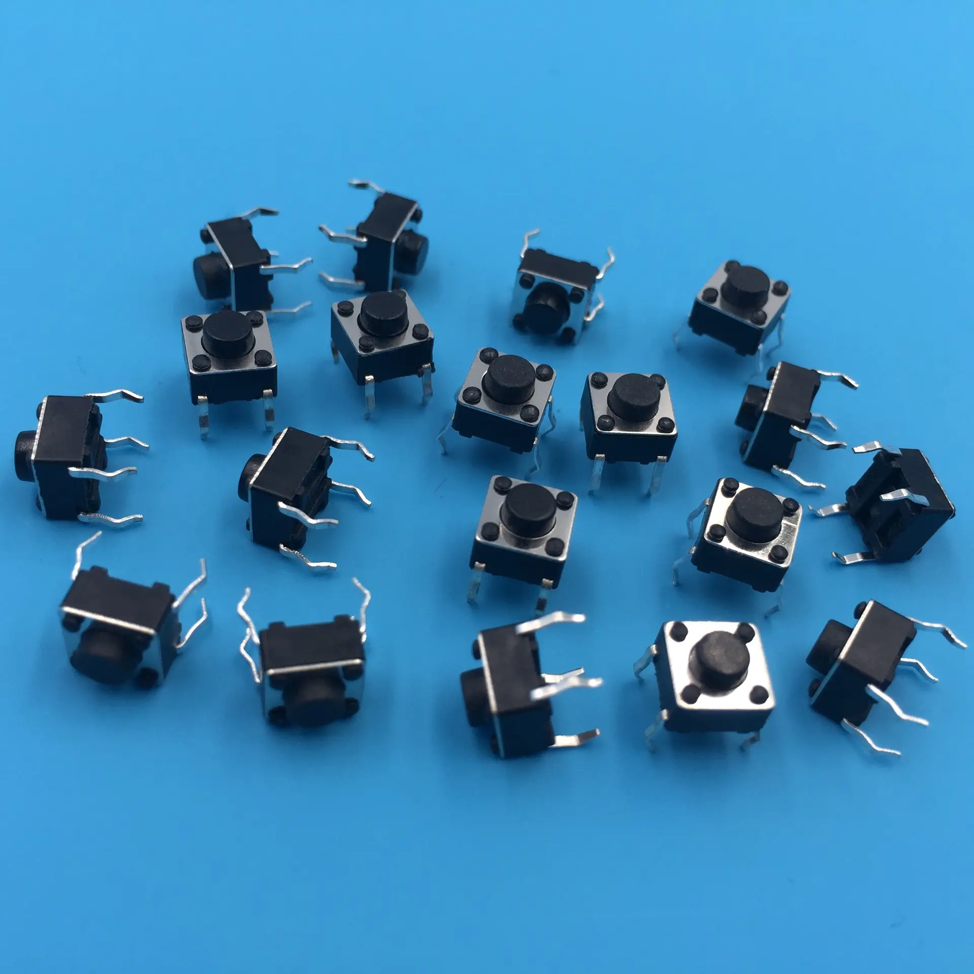 Most buttons come with two sets of pins (contacts). When you press the button, it connects the two pins in a pair, allowing current to flow.
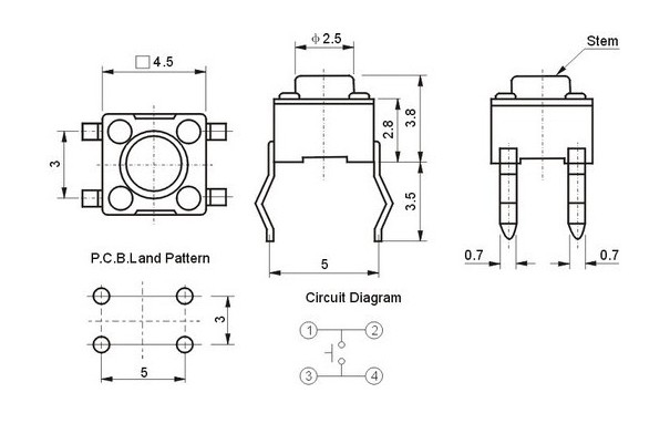 For those common 4-pin tactile buttons, here’s a neat tip: the pins that are farther apart are internally connected, and the ones closer together form the switching pair. Ideally, use a multimeter to test the connections — but if you’re just prototyping and need a quick setup, connecting the pins diagonally always works!
Now here’s the best part —
👉 If you’re using an ESP32 extension board, everything gets even easier.
You don’t need to worry about resistors in series or confusing pin connections. The extension board handles the pull-up/pull-down resistors and power routing for you, making your setup much safer, cleaner, and far less prone to wiring mistakes. It’s a great way to reduce the chances of errors or damaging your board.
2️⃣ 🔌 Wiring the Button
🧩 Option A: Using an Extension Board (Recommended for Beginners)
If you’re using an ESP32 extension board, good news! 🎉
- You don’t need to worry about pull-up resistors.
- Just use female-to-male jumper wire and connect corrdingly.
| LED Board Pin | ESP32 Pin | |—————|——————| | GND | GND | | 5V | 5V | | LED1 | GPIO2 (D2) | | SW1 | GPIO14 |
- The board handles resistor setup internally, making things safer and more reliable.
🧪 Option B: Breadboard Wiring (Manual Setup)
| Component | ESP32 Pin |
|---|---|
| One side of button | GND (ground) |
| Other side (diagonally) | GPIO14 |
| Pull-up resistor (10kΩ) | Between GPIO14 and 3.3V |
| LED1 | GPIO12 (D12) |
🔧 Or, skip the external resistor by using INPUT_PULLUP mode in your code.
Note: be careful with the direction of LED and remeber to connect a resistor in series with the LED
- Long leg = positive (anode)
- Short leg = negative (cathode)
Basic Diagram (Text version):
 3.3V ──┐
        │
       [10kΩ]
        │
GPIO14 ─┴──── Button ───── GND
3️⃣ 🧠 Arduino Code: Read Button + Control LED + Print to UART
int buttonPin = 14;  // GPIO connected to the button
int ledPin = 2;      // Built-in LED (change if using external)

void setup() {
  Serial.begin(115200);              // UART Serial output
  pinMode(buttonPin, INPUT_PULLUP);  // Use internal pull-up resistor
  // pinMode(buttonPin, INPUT_PULLDOWN);     // Use internal pull-down resistor //uncomment to see what happens
  pinMode(ledPin, OUTPUT);           // LED output
}

void loop() {
  int buttonState = digitalRead(buttonPin);  // Read button

  // Note: LOW = Pressed, because of pull-up logic
  Serial.print("Button is ");
  Serial.println(buttonState == LOW ? "PRESSED" : "RELEASED");

  // Turn on LED when button is pressed
  digitalWrite(ledPin, buttonState == LOW ? HIGH : LOW);

  delay(100);  // Avoid spamming output
}
📥 Configure Input Modes in Arduino (ESP32)
You can configure GPIO input using pinMode() in Arduino:
pinMode(14, INPUT);           // Basic input – needs external resistor
pinMode(14, INPUT_PULLUP);    // Enables internal pull-up resistor
pinMode(14, INPUT_PULLDOWN);  // Enables internal pull-down
🧲 INPUT
- No internal resistor.
- You need to add an external pull-up or pull-down resistor.
🔼 INPUT_PULLUP
- Uses the internal pull-up resistor.
- Pin defaults to HIGH (3.3V).
- When you press the button, it gets pulled LOW (0V).
🔽 INPUT_PULLDOWN
- Uses the internal pull-down resistor.
- Pin defaults to LOW (0V).
- When you press the button, it gets pulled HIGH (3.3V).
Give it a Try !
pinMode(14, INPUT_PULLDOWN);
📊 Reading the Pin
Use digitalRead(pin) to get the current state:
int state = digitalRead(14);
if (state == HIGH) {
  Serial.println("Pin is HIGH (3.3V)");
} else {
  Serial.println("Pin is LOW (0V)");
}
🧠 Tip: Know Your Logic!
| Mode | Default State | Pressed State |
|---|---|---|
| INPUT + pull-down | LOW | HIGH |
| INPUT_PULLUP | HIGH | LOW |
So depending on the setup, pressed = HIGH or LOW. Make sure your code matches your hardware.