🌈 Running Light Experiment (ESP32 + Arduino)
In the previous lesson, we learned how to blink a single LED. This time, we’re going a step further and building a running light effect using multiple LEDs. It’s a classic project that helps you understand arrays, loops, and GPIO control in embedded systems.
🔧 Hardware Circuit Design
Option A: Use Your ESP32 Extension Board (Recommended)
✅ Wiring Plan
Use female-to-male jumper wires
| ESP32 GPIO Pin | ESP32 Label | Connects To | LED on Module |
|---|---|---|---|
| GPIO13 | D13 | LED1 | D1 (Red) |
| GPIO12 | D12 | LED2 | D2 (Yellow) |
| GPIO14 | D14 | LED3 | D3 (Yellow) |
| GPIO27 | D27 | LED4 | D4 (Green) |
| GND | GND | GND | Common GND |
⚠️ Important: The LED module expects you to connect each GPIO pin to the LEDx pin (anode), and share a common GND with ESP32.
🧠 Understanding the Circuit
Each LED already has a series resistor on the board, so you can connect the ESP32 GPIO pins directly to the LEDx inputs — no external resistors needed.
Option B: Use a Breadboard (Alternative)
🧰 Bill of Materials (BOM)
| Item | Quantity |
|---|---|
| 5mm LED (through-hole) | 5 |
| 1kΩ Resistor | 5 (or 1 shared) |
| Jumper wires | Several |
| Breadboard | 1 |
Each LED’s positive leg (anode) is connected to a different GPIO pin. Each LED is connected in series with a resistor, and the negative leg (cathode) goes to GND.
⚠️ You can use a single resistor for all LEDs if you multiplex carefully, but we recommend one resistor per LED for safety and clarity.
🧩 Using Your Extension Board
If you’re using your custom ESP32 extension board, simply plug the LEDs directly into the labeled GPIO ports like this:
[D13] --> LED1 (anode)
[D12] --> LED2 (anode)
[D14] --> LED3 (anode)
[D27] --> LED4 (anode)
[D26] --> LED5 (anode)
Each LED cathode --> Resistor --> GND
✅ No breadboard required if your extension board exposes GPIO headers!
⚠️ Still remember to add resistors to limit current.
💻 Software: Program Design
We’ll walk through 3 variations of the running light effect:
🔹 1. Standard Running Light (One-way ON → OFF)
Each LED turns on one by one from left to right, then turns off in the same order.
// Define the GPIO pins connected to the 4 LEDs
int pin_list[4] = {13, 12, 14, 27};

// Calculate the number of LEDs using the array size
int size = sizeof(pin_list) / sizeof(pin_list[0]);

void setup() {
  // Set each pin in the list as OUTPUT
  for (int i = 0; i < size; i++) {
    pinMode(pin_list[i], OUTPUT);
  }
}

void loop() {
  // Turn on LEDs one by one from left to right
  for (int i = 0; i < size; i++) {
    digitalWrite(pin_list[i], HIGH);  // Set the pin HIGH to turn on LED
    delay(50);                         // Wait for 50 milliseconds
  }

  // Then turn them off one by one from left to right
  for (int i = 0; i < size; i++) {
    digitalWrite(pin_list[i], LOW);   // Set the pin LOW to turn off LED
    delay(50);                         // Wait before turning off next LED
  }
}
🔁 2. Back-and-Forth Running Light (ON → ← OFF)
Now we make the LEDs light up from left to right and then back from right to left, like a wave.
int pin_list[4] = {13, 12, 14, 27};
int size = sizeof(pin_list) / sizeof(pin_list[0]);

void setup() {
  for (int i = 0; i < size; i++) {
    pinMode(pin_list[i], OUTPUT);  // Initialize all LEDs as OUTPUT
  }
}

void loop() {
  // Turn on LEDs from left to right
  for (int i = 0; i < size; i++) {
    digitalWrite(pin_list[i], HIGH);
    delay(100);
  }

  // Then turn them off from right to left (reverse)
  for (int i = size - 1; i >= 0; i--) {
    digitalWrite(pin_list[i], LOW);
    delay(100);
  }
}
➡️ 3. Shifting Light (Single LED “Moving”)
This version creates a “moving dot” effect. Only one LED is on at any time, giving a clean shifting illusion.
int pin_list[4] = {13, 12, 14, 27};
int size = sizeof(pin_list) / sizeof(pin_list[0]);

void setup() {
  // Set all pins as OUTPUT
  for (int i = 0; i < size; i++) {
    pinMode(pin_list[i], OUTPUT);
  }
}

void loop() {
  for (int i = 0; i < size; i++) {
    // Turn on the current LED
    digitalWrite(pin_list[i], HIGH);

    // Turn off the previous LED
    if (i > 0) {
      digitalWrite(pin_list[i - 1], LOW);
    } else {
      // If it's the first LED, turn off the last one to complete the loop
      digitalWrite(pin_list[size - 1], LOW);
    }

    delay(250);  // Slower speed to visualize movement
  }
}
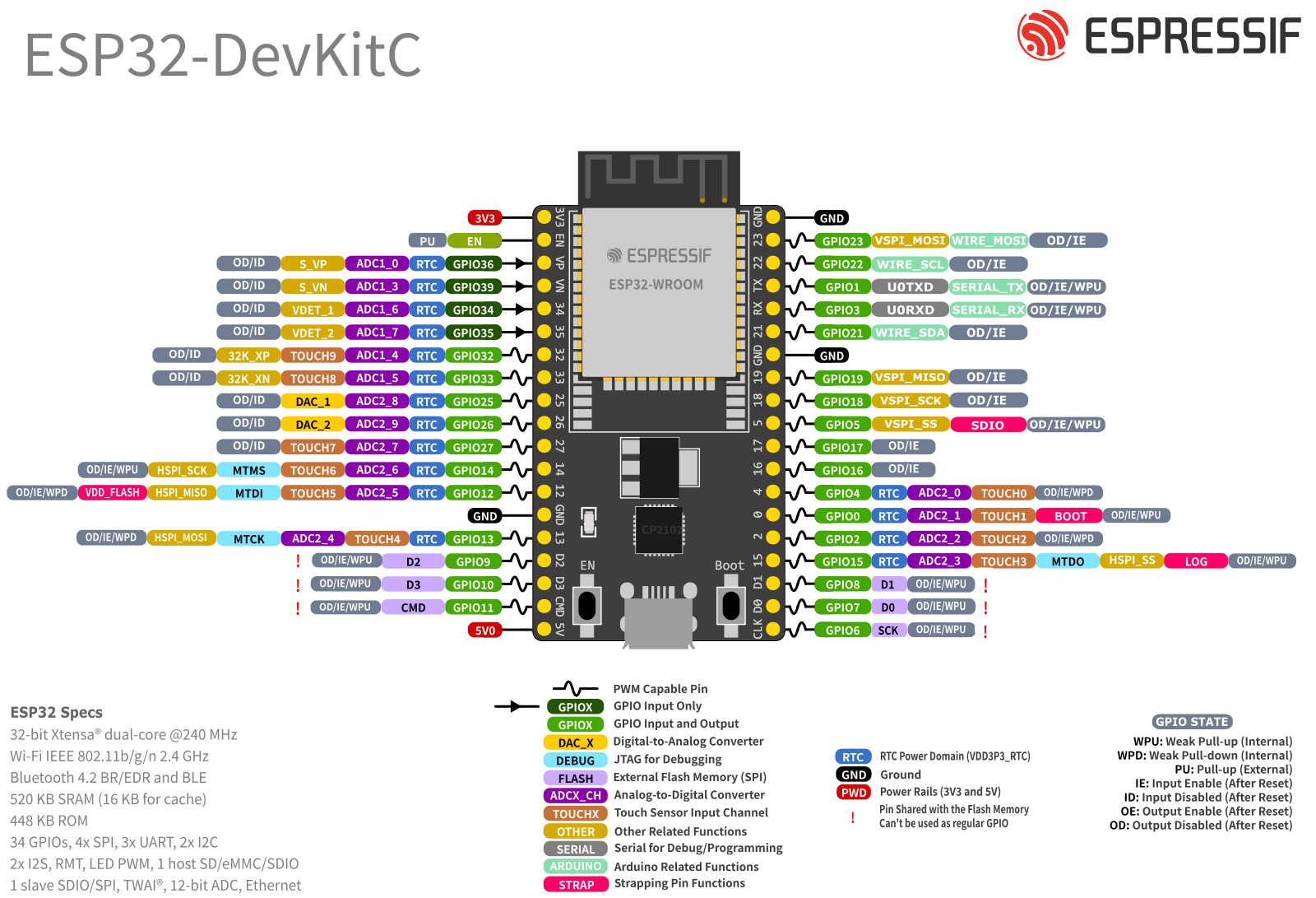
📍 GPIO Pin Reference
Need help locating the pins?
Want to use other GPIO pins?
🔗 ESP32 DOIT Dev Board Pinout Diagram :
Using ESP32S3 ? ESP32-S3 Datasheet
Using ESP32C3 ? ESP32-C3 Datasheet
Use this guide to verify that the GPIO pins you selected are safe and not reserved for boot or special functions.
🧠 Bonus: What’s the Principle Behind a Running Light?
This project is all about:
- GPIO Output: We use GPIOs to send voltage to LEDs.
- Arrays: Store multiple pin numbers to simplify control.
- Loops: Iterate through the array to light up LEDs in sequence.
- Timing: Use
delay()to control the speed of the lighting effect.
You’re using code to create time-based visual patterns — it’s how things like light strips and LED displays are made!