💡 GPIO Output – Light Up and Blink an LED
When learning any microcontroller, one of the simplest yet most essential experiments is controlling an LED using a GPIO pin. This lesson will walk you through how to light up and blink an LED on the ESP32, and now includes instructions on using the custom extension board you designed!
✅ By the end of this tutorial, you’ll:
- Understand GPIO output basics
- Light up and blink an LED
- Learn how to use your custom extension board
- Get familiar with ESP32 pin configurations
🧠 Basic Concepts
1. What is a GPIO Pin?
GPIO stands for General Purpose Input/Output. These are the pins on the ESP32 that can either send or receive electrical signals.
On the ESP32 board, you’ll notice pins labeled with “D” like D2, D4, D15 — these are GPIO pins. Today, we’ll focus on output, where a pin sends out a voltage signal.
⚡ What is a voltage level?
Microcontrollers “talk” using electricity in the form of voltage levels, often referred to as logic levels in digital electronics.
In simple terms:
- HIGH = On = Voltage Present (usually 3.3V on ESP32)
- LOW = Off = No Voltage or near 0V
By changing the voltage on a GPIO pin, we can turn things on and off. For example:
- Sending a HIGH signal to an LED pin makes it glow.
- Sending a LOW signal turns it off.
Exact thresholds may vary slightly — feel free to test and confirm!
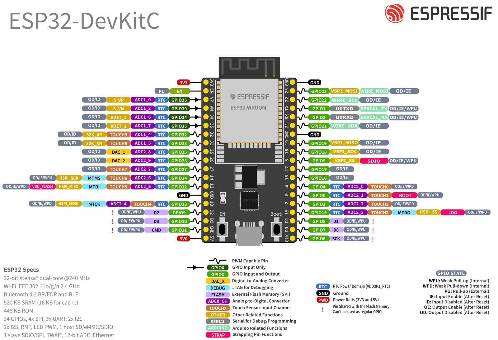
📐 How Many GPIOs Are There? The ESP32 has 30+ GPIO pins, and each can serve different roles:
- Some are digital-only
- Others support analog input, PWM output, I²C/SPI/UART communication, etc.
Not all pins are equal — some are input-only, some are strapped (used during boot), and some should be avoided during startup. 🧭 Use this pinout guide to check which pins are safe for your specific application:
🔗 ESP32 Pinout Guide (Random Nerd Tutorials)
2. What is an LED?
An LED (Light Emitting Diode) is a tiny light source that emits light when current flows through it in the correct direction.
- Needs only about 5mA to light up
- Too much current can burn it out, so we add a resistor to limit the current
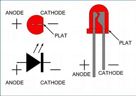
- LED has two legs:
- Long leg = positive (anode)
- Short leg = negative (cathode)
- Current flows from anode to cathode only
When lit, an LED typically shows a forward voltage drop of about 1.7V.
🔌 Hardware Setup
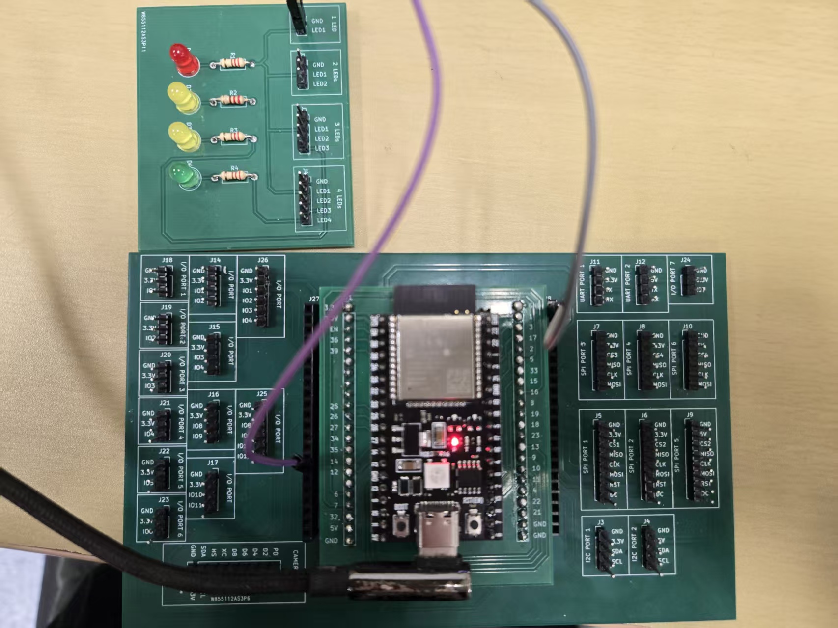
Option A: Use Your ESP32 Extension Board (Recommended)
The extension board is designed to make wiring easier and reduce the possibility of damaging the components.
✅ Steps:
Use female-to-male jumper wires to make the following connections:
| LED Board Pin | ESP32 Pin |
|---|---|
| GND | GND |
| LED1 | GPIO12 (D12) |
Option B: Use a Breadboard (Alternative)
If you don’t have your extension board with you, here’s how to wire it on a breadboard:
📋 Bill of Materials (BOM)
| Item | Quantity |
|---|---|
| LED (through-hole) | 1 |
| 1kΩ Resistor | 1 |
| Jumper wires | Some |
| Breadboard | 1 |
🧩 Circuit Wiring
- Connect LED’s positive leg (anode) to D12 on the ESP32
- Connect a resistor in series with the LED
- Connect LED’s negative leg (cathode) to GND
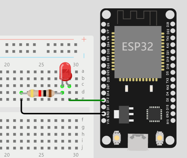 ⚠️ Important: Always include the resistor, or your LED could burn out due to excess current!
💻 Software Design
1. Light Up the LED
To light up the LED:
- Set the GPIO pin (D12) as output
- Write a HIGH signal to the pin
// Set LED pin
int led_pin = 12;

void setup() {
  pinMode(led_pin, OUTPUT);       // Set pin as output
  digitalWrite(led_pin, HIGH);    // Turn on the LED
}

void loop() {
  // Nothing here for now
}
Upload this code using your Arduino IDE — the LED should turn on!
2. Make the LED Blink
Now, let’s make it blink! Blinking means:
- Turn the LED on
- Wait for a second
- Turn it off
- Wait again
- Repeat
Here’s how to do it:
// Set LED pin
int led_pin = 12;

void setup() {
  pinMode(led_pin, OUTPUT);  // Set pin as output
}

void loop() {
  digitalWrite(led_pin, HIGH); // Turn on LED
  delay(1000);                 // Wait 1 second
  digitalWrite(led_pin, LOW);  // Turn off LED
  delay(1000);                 // Wait 1 second
}
Upload the code — you’ll see your LED blinking on and off every second.